Consideration of Key Factors

Before RF Sealing Your Product.

RF sealing medical products require a stable process control to meet the product quality requirements. The slightest variation in material properties, operating conditions, RF power or process control variables can affect the product quality.

Control of the critical elements below, is essential to achieve repeatable RF sealing process:

Interacting Elements

  • Material
  • RF Sealing Die
  • RF Sealing Press Integrity
  • RF Energy Source, Generator
  • RF Sealing Process Control Setup

Shuttle RF Welders

The Medical Device industry uses common FDA approved RF sealable materials.

Most solution bags use PVC and EVA materials. The air bladders, such as blood pressure cuffs, tourniquet cuffs or heat-packs use PVC or TPU coated fabric (Nylon) materials. Most orthopedic products use TPU foam or fabric materials. Once you know the application and type of material next you have to design the bonding strength to hold the liquid or air media.

For high pressure applications it is critical to use stronger material like TPU.

For light pressure applications PVC should be adequate. By increasing the material thickness it will increase the bond strength.

Material Sealability Chart for RF Sealing Process in Alphabetical Order

Material Type

Excellent, Good, Fair, Poor or None 

APET

Good

EVA

Good

EVOH (Ethyl Vinyl Acetate)

Fair

PET (Polyethylene Terephthalate)

Good

PETG (Polyethylene Terephthalate Glycol)

Excellent

Polyester

Poor

Polyurethane

Fair

Polyurethane foam

Poor

Polyurethane-vinyl film

Good

Polyvinyl Acetate

Good

Polyvinyl Chloride (PVC) flexible, clear

Excellent

PVC color

Excellent

PVC opaque

Good

PVC semi-rigid

Good

PVC rigid

Fair

PVC coated material (fabric, cloth or paper)

Excellent

PVC adhesive emulsions

Excellent

Saran (Polyvinylidene Chloride)

Excellent

RF Weld Integrity

Based on Material Properties

As shown in the example picture there are many types of RF welded solution bags in the industry that are manufactured using PVC, EVA or TPU materials. Most solution bags bags come with tubing ports for liquid or air depositions. The RF sealing of ports without any leaks is the most important task in the industry in addition to controlling the perimeter seal thickness to prevent any weak seals or material breakage from the seal edge or corner.

When bonding two material layers, we compress them and as the material melts the press stops at a fixed height, which is controlled mostly by Hard Stops. The seal thickness can range from 50% to 70% of the overall combined material thickness. A few factors control the seal thickness:

  • Material thickness
  • Material Type
  • Pull Strength Requirement
  • Liquid or Air Handling / The Purpose

Stronger materials like TPU films can go down to 50% seal thickness.

PVC materials are sealed up to around 60% RF sealed thickness. 

Melting evenly of top and bottom materials: Besides the seal thickness we must also consider a proper path for material flow, which can help the seal strength by forming an nice round bid like a bobble versus a shape of leaps uneven material flow on the top versus on the bottom.

Different Thickness Materials: RF welding energy always concentrates on the center of the material layers. If the bond surface is not in the center, simply because one material is thicker then the other we have to shift the RF energy concentration either by adding more material (buffer) or increase the die temperature on the thin material side.

Different Type of Materials: When bonding two different materials, for example TPU to PVC, it is important to setup the process such that the high Glass Transition Temperature (Tg) material heats first and conducts heat to the lower Tg materials. If this is not controlled properly the lower Tg material will collapse by melting first and the section will loos the compression force, which is critical to achieve the proper bond strength. When bonding 2 different materials it is impossible to get homogeneous bond where the materials are evenly mixed on the bond surface. The weld strength can also be altered by playing with the timing and power allowing enough time for the two materials to reach the melting temperature while maintaining the consistent pressure.

Same type but Rigid to Soft Material bonding: When bonding rigid and soft materials, for example rigid PVC connector to soft PVC film. Like the previous example of using different materials, in this case the same Tg difference applies.  When heating rigid material, it will collapse by melting first and the section will loos the compression force.  We must employ different substances (buffer materials) to allow heating the soft PVC at the same time to create the leak free bond. It is also critical to have perfect fit of supporting mandrel. If the mandrel or electrode don't make a good contact with the rigid component the material will heat and burn quick because some sections don't loos heat through the metal surface.

Material Factors

Material properties that can affect the RF seal strength & elements to control the process

Material Layers

  • Thickness Variations (thick-thin)
  • Physical property mismatch (rigid-soft)
  • Tg mismatch (different melt points)
  • Chemical property mismatch

Control Elements

  • Die Surface
  • Die Temperature
  • Type of Buffer Material
  • Compression Force
  • RF Power & Time

Most material variations can be resolved by proper die design and implementation of buffer materials or thermal conditioning of dies.

RF Welding Die Design


What is RF welding die or mold? Generally when products are assembled or bonded together the joining process uses some kind of mold to join the to halves.

The RF welding dies are used for joining to tin flexible plastic materials to form a container used in the following applications:

  • Liquid handling bladder
  • Air pressure cuff or air bladder
  • Cushions filled with liquid jell
  • etc...

The RF welding die usually has a raised thin edge that is used for sealing the product perimeter.The seal width is determined by the product designers, which can range from 0.040 to 0.375". Most liquid handling medical bags use 0.05-0.125" Seal thickness. The RF seal width for air bladders or cushions may go up to 0.25" to increase bond areal strength and allow further die cutting of the edges.

During the RF welding process because of some material properties the dies are designed to seal and cut the perimeter of the product using with a knife edge, which penetrates into the material down to 0.003" to allow tearing the excess material. The knife edge is either machined or a separate tear seal blade is attached around the perimeter of the die.

The Tear Seal Materials are:

  • PVC
  • EVA
  • EVOH

The materials that have more elasticity are very difficult to tear-seal because the 0.003" thick tear section stretches like a rubber. The elastic materials like TPU and other coated fabrics are mostly die cut after the RF sealing process.

RF Sealing Die Materials
RF Sealing dies can be constructed using the following materials:

Materials

  • Brass
  • Aluminum
  • Naval Bronze
  • Stainless Steel

RF Welding Dies

Manufacturability: The aluminum is the cheapest and easiest material for manufacturing the dies. Brass or Naval Bronze are more difficult, because of internal stresses the final shape may warp during machining and proper process control is essential to achieve perfectly parallel surfaces.

Seal Surface Finish: The Sealing surface must be free of any burs or sharp edges or corners to prevent arcs. The sides of the RF sealing rails must be rounded evenly across the perimeter to help even bid flow and formation of melted material.

Material Conductivity: The brass die is a better conductor and may result in less energy losses compared with aluminum dies. 

Arc Damage: The arc will create more damage on the aluminum surface compared with brass because the aluminum melting temperature is lower then brass.

Buffer materials: The buffer usage serves several purposes:

  1. Increases Voltage Break Down Resistance thus reducing the chance of arcs.
  2. Acts as an insulator to reduce the material temperature loss through the die contact surface thus reduce the need for too much power, specially for thin materials.
  3. Can act as an added thickness on the thin material side to balance the RF energy concentration on the bond surface.

RF Welding Press Construction

RF Welders use C-frame or H-frame press station energized by Air Cylinder, Hydraulic Cylinder or Electric Cylinder (Servo Slides). Based on the surface area of the sealed product the press needs to apply sufficient force to clamp and seal the product. Air cylinders are standard solution and provide sufficient pressure for most applications. Hydraulic press is used for cutting and embossing applications, which require more force cutting or pressing force. The Electric slides are used in rare applications where applied pressure on the material is critical or position control is done by the slide. When using Air cylinder the seal thickness is controlled by hard stops as part of the die design.

The RF sealing press base frame is usually grounded and acts as RF ground. If for some reason the RF ground is isolated from the chassis ground it will create potential difference and cause an arc or shock.

RF input to the press is connected to the back or to the center of the of the upper platen.

The upper platen is the plate where the top RF sealing die is mounted. The RF upper platen is isolated from the press ram to prevent RF energy losses through the Air cylinder mounted to the chassis.

RF Connections
RF Connections and paths to ground must be constructed non-corrosive material that are very good conductors.

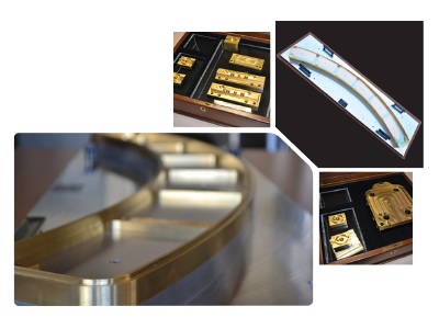
RF Conductor Materials

  • Brass
  • Aluminum
  • Copper Foils
  • Stainless Steel

Seal Failure Causes

  • Surface Corrosion
  • Uneven Contact Surfaces
  • RF Connection Modifications

Rotary RF Welders

Press Chassis: The press design is critical to make sure the construction does not deform during the sealing cycle when full pressure is applied. We have notice seal thickness variation because some C-frame presses (that come with minimum wall thickness) band back during the sealing time.

Surface Finish: The RF sealing presses use steel welded frame construction and in many cases the surface is not painted to act as ground. Over time the surface corrosion causes weakening of seal integrity because it adds resistance in the RF signal path to ground.

Uneven Surfaces: It is hard to achieve perfect flatness sometimes and if two RF conducting surfaces don't make good contact the areas that are not making connection will collect charge and start arcing. If the surface uses low melting temperature material like an aluminum the surface will start wrinkling and will make things even worse. It is not a good practice to sand the surface since it will create even more uneven sections.

Replacing RF Connections: The RF welders usually use Copper or Brass Foil Connections to transfer the RF signal from the generator to the moving upper platen. These connections may be 1" to 6" wide and cut to a fixed length. If these connections break due to the press movement it is critical to use the exact size replacement. If you change the width or the length of the connection the impedance will change and any RF matching circuit you use will have to be tuned to achieve the resonance. It is also important to maintain the same curve shape, because it can form a capacitance with different grounded surface and change the circuit impedance as well.

RF Generator Use in

RF Welding Process

Introduction to RF Generator types:

RF welding generators are the source of RF energy that melt the clamped material between the RF welding dies and forms the perimeter of solution bags or air bladders. The amount of RF power required in the welding process is determined mainly by the seal area (the overall perimeter or seal length times the weld thickness).

  1. Most RF welding systems, specially the older styles, use oscillator tube RF generators. The RF frequency is matched by the resonator circuit (LC by adjusting the L) and slightest change in product size will change the resonant frequency causing process inefficiency.
    The Power level is controlled by the coupling capacitor which is adjusted by mechanical screw coupled to a motor or a knob for manual setup. For some dual cycle applications an air cylinder may be used to move the capacitor plate back and forth to achieve the required power.
    The sealing power is set by turning the knob and visually monitoring the Plate Current Meter.
  2. The newer style RF welders use  Solid State generators, which are RF signal amplifiers that use a fixed frequency and have the ability to auto tune the frequency mismatch by an automatic match networks. The solid state generators are more stable offer higher level process consistency and come faster arc control circuit, which hardly will ever damage the dies due to arcs.
    The RF sealing power is set by 0-10VDC by the PLC and is very easy to control and validate the process. The feedback is pure power in watts on the generator screen or operator interface panel.
  3. The ONEX style RF welders use  Hybrid generators, which are also RF signal amplifiers that use a fixed frequency and have the ability to auto tune the frequency mismatch by an automatic match networks.
    The difference between Hybrid and full Solid state The solid state generators are more stable offer higher level process consistency and come faster arc control circuit, which hardly will ever damage the dies due to arcs.
    The RF sealing power is set by 0-10VDC by the PLC and is very easy to control and validate the process. The feedback is pure power in watts on the generator screen or operator interface panel.
Pros and Cons
All the generator types can do the job. The questions is, do you need more control over your process? Which generator technology is the best fit for you?

Old Oscillator Tube Technology

  • Easy single knob power control
  • Constantly requires tweaking
  • Can damage dies due to arcs
  • Does not require an Auto Tuner
  • Requires people with "Tribal Knowledge" for maintenance

Solid State RF Amplifiers

  • Precise Process Control
  • Requires an Auto-Tuner
  • Fast Arc shutdown system
  • Uses several combined RF amps.
  • Susceptible to high reflected power
  • Can only be repaired by the manufacturer

Hybrid RF Amplifiers (ONEX RF)

  • Precise Process Control
  • Requires an Auto-Tuner
  • Fast Arc shutdown system
  • Uses SS Amp and final Tube Amp.
  • Not susceptible to high reflected power
  • Can be repaired onsite by techs trained by ONEX RF.

RF Welding Generator Compare

We built the Hybrid RF generator technology to be able to set the process parameters once and never worry about changing them after the validation. Plus, we are able to guarantee the dies, we manufacture, for 10 years if they are used on ONEX RF welders only.

Portfolio of ONEX RF Welders

RF Welder Brochure Cover Page

RF Welding Solutions

ONEX RF offers various RF welding systems for the medical and automotive products manufacturers. 
Some of the products we have sealed in the past are blood, urine or other solution collection bags, and car seat air bladders.
View the brochure for more system options.

Other Services:

  • RF Welding Die Design and Fabrication
  • Sample Runs for Evaluation
  • Process Development
  • Validation Support


View RF Welder Brochure

CONTINUE LEARNING

RF Welder Theory
RF Welder Setup

Contact Request Form

For quick response, please provide details of your product, process needs, and full contact information.

Customer-Service-Contact-Us-Form

For application related questions, you can always reach us by phone at +1(626)358-6639.

We offer excellent service:

  • Die Prototyping
  • Evaluation Samples
  • Full Process Development
  • Turnkey RF Welding Machine Solutions

We look forward to working with you soon.


EXPECT ONLY EXCELLENCE