RF Welding Generators are used in the RF Heat Sealing process to melt plastics materials, comprised of polar molecules. Most RF sealing processes use 27.12MHz high frequency. The same frequency is also used in the Ham-Radio Communications Industry hence where the High Frequency (HF) is referred to as Radio Frequency (RF).
ISM Band Frequencies (Industrial Scientific Medical): The frequency used in the RF welding systems is regulated by FCC and generators must comply with ISM frequency guidelines. The large RF welders will usually use 13.56MHz frequency if the platen size exceeds the 1/4 wavelength of the frequency.
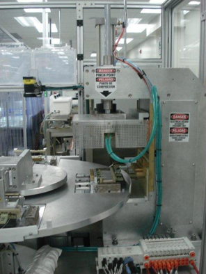
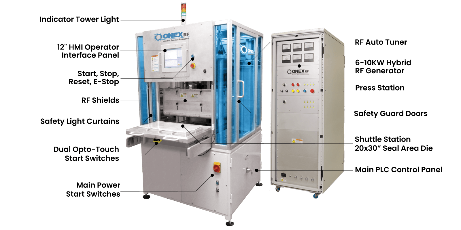
RF Sealing Press: The RF Welding station is a stand-alone pneumatic or hydraulic press, which compresses the plastic material between two molds, referred to as RF sealing dies.
RF Welding Process: In simplest terms, RF welders operate much like microwave ovens that heat food. The Microwave excites the polar water molecules and heats the food.
The RF welder on the other hand heats the plastic material that has polar molecules, which get excited by the high frequency energy.
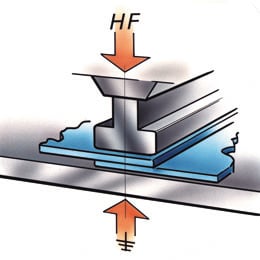
When RF energy is applied to the compressed material between the RF sealing die surfaces (RF Electrodes), in this case the die surfaces act as capacitors and the plastic material as the insulator dielectric materials, the polar molecules get polarized and start oscillating in the alternating electromagnetic field. This movement or inner molecular friction and dielectric loss material heats up and melts the material. As material softens the press further advances to form the bonded section, defined as RF weld thickness. Once the RF energy is interrupted the material cools down by loosing heat through the dies metal surface.