Common Practices for Calculating

RF Power Based on Seal Area

RF Power is direct proportional to the seal area. The seal area is the sum of all the areas of seal sections (Seal width multiplied by Seal length) AS=WS x LS.

Additional power is required for the products that require sealing plus cutting the perimeter using a tear seal blade.

The common practice for calculating the required RF power for tear seal is by multiplying the total seal length or the perimeter by 1/8. This will give you the equivalent seal area for the tear seal, which will be added to the perimeter seal area to calculate the total RF power.

Lets assume we want to make a flat seal of 1 square inch material and need to achieve good seal in 3 seconds.

As a general rule the RF power required for the materials below are:

RF Power Required

  • PVC materials 250-300 watts

  • EVA materials 300-400 watts

  • TPU materials 400-500 watts

Applications notes:

RF Sealing Thin Materials: In a few applications where very thin TPU materials are used like 0.002" thick can be very difficult to seal. The material is so thin that the heat generated by the RF energy dissipates through the die immediately if proper insulator is not used. Thin material sealing will require extremely more power than above 4-5mil thick materials.

Heated Upper Platen (Die): It is recommended to heat the upper platen slightly higher then the room temperature and keep it constant. This practice helps achieving stable seal process because when the machine starts operating after several hours shut down, the die temperature is equal to the room temperature.  After several RF cycles, as the material heats and cools, the die temperature slowly will rise due to residual heat build up, and will start melting the material faster. This condition can be controlled by using external thermal device to maintain constant temperature. Heated upper platen may also help reduce the overall cycle time and RF power.

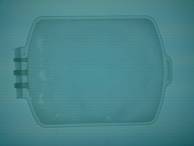
RF Welding Large Product: When sealing large bladders the RF frequency become critical because of the 1/4 wave. The product must be smaller than the 1/4 wavelength of the frequency to prevent uneven potential difference in various section of the perimeter. Also the RF feed  location into the upper platen may affect the even RF energy distribution across the product seal area. It is a common practice in the industry to use shims by lifting the die section to achieve the seal strength, which can be very time consuming process every time you change the setup. ONEX RF uses different type of RF feed line, which eliminates the need for shimming if the dies are correctly manufactures.

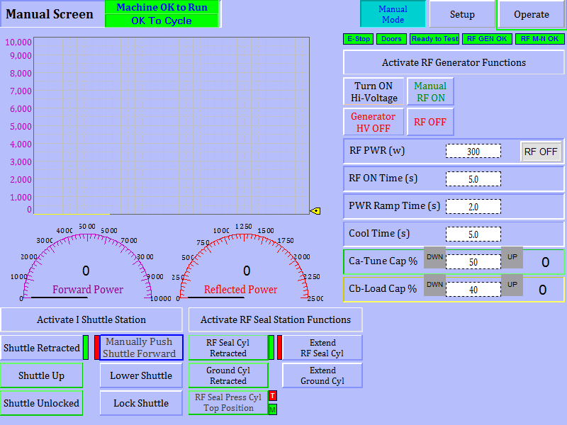
Process Tuning: Since ONEX RF uses hybrid generator, the ONEX RF welders come with Matching Network, which automatically matches the impedance when sealing the bag and the port in two cycles. This device also eliminates the possibility of process variations when RF welder requires multiple setups to run different size bags.

Because the port seal area is considerably smaller than the perimeter seal area, even though the auto tuner has the bandwidth to automatically match the difference ONEX RF may add a small inductor/capacitor network to better control the matching  time.

Let's Do Some

Basics Calculations

Let's assume we are going to RF seal a 500ml PVC blood bag with 3 ports. When the process requires a tear seal we can not use any buffer material on top rather we will need a buffer material (Mylar) on the bottom of the bag so we can tear seal against it. (The thickness of the Mylar must be considered as overall die thickness to properly set the hard stops to control the final dept for tear seal blades. The blade must be parallel without any bumps or sharper edges to prevent arcing. 

The bag will be RF sealed in 2 cycles:

  • First, port seal cycle
  • Second, perimeter seal cycle

Dual Cycle RF Sealing Switch: The ports and perimeters are RF sealed with a single die that has mandrels inside the ports (bushings). The RF energy is applied to the bag in two cycles through an RF Switch. The RF switch is a pneumatically activated mechanism that switches the RF signal from one side to another, let's temporary name them A and B. When sealing the ports the RF signal comes from the A connection and connects to the port sealing mandrel, the upper and lower dies are connected to ground. When RF energizes the the dielectric material clamped around the mandrel by the dies will start melting and bonding the bushing to the outer film top and bottom layers.   After the Port RF seal cycle the RF Switch will energize the B side the RF power, while the die is closed, will apply to the upper die and A connection will not receive RF signal any more and bottom die will be connected to the ground. When RF signal is applied to the upper die the dielectric material, between the upper and lower dies, will melt and bond the perimeter of the bag.

Perimeter Seal Power: See the  formula in the above section. 

Port Sealing RF Power: Usually the RF power for sealing the ports is small like 100-150 watts, but because the RF energy is transferred through coax lines or mechanical connections, it causes energy losses (500w/12ft coax cable) thus it will require slightly higher power like 250-300 watts per port, higher power will help reduce the cycle time. Although high power shorter seal cycle may cause uneven seal thicknesses. It is critical to pay attention to even material flow to prevent any channel leaks around the ports.

RF Seal Area Calculation

Perimeter Seal Area

  • Seal Length x Seal Width = Seal Area
    33.5 x 0.100 = 3.35 sq.in
  • Tear Seal Length x 0.125 = Tear Seal Area
    22.6 x 0.125 = 2.825 sq.in
  • Hanger Seal Length x Seal Width = Hanger Seal Area
    2.15 x 0.100 = 0.215 sq.in
  • Hanger Tear Length x 0.125 = Hanger Tear Seal Area
    1.85 x 0.125 = 0.235 sq.in
  • Sum of Total Seal Areas
    3.35 + 2.825 + 0.215 + 0.235 = 6.625 sq.in

Port Seal Area

  • 3.14 x Port Seal Diameter x Seal Length = Port Seal Area
    3.14 x 0.260 x 0.350 = 0.285 sq.in
    3.14 x 0.350 x 0.350 = 0.385 sq.in
  • Sum of Total Port Seal Areas
    2 x 0.285 + 0.385 = 0.955 sq.in
Hanger-Seal-only-bag

Calculating RF Seal Power

Based on the RF Seal Area Calculations we need to multiply the total RF Seal area by 250 or 300 watts per square inch area.

The Perimeter RF Seal Power will be: 6.625 x 250 = 1.655 watts.

Ports RF Seal Power will be: 0.955 x 250 = 240 + 250 = 500 watts (add 250 watts for RF power losses).

RF Welding Process

Parameter Finding

When we start finding the process parameter, we always start in the manual screen because it's easier to quickly set the process parameters and make quick seals and see how the material behaves. The goal is to clamp the press and apply minimal RF power until it melts. When the material starts melting by keeping the RF power on for about 3-5 seconds the auto tuner will find the best tune point and capacitors will stop moving. We then use the capacitor values and set the initial set points by increasing the value by 5. Once the Tuning is set we can start playing with the parameters.

We load material and by using the manual station buttons.

  1. We lock the shuttle
  2. Extend the ground return.
  3. Extend the press down
  4. Turn High Voltage ON
  5. Set the RF power 25-30% lower than the Seal Area Calculated Power.
  6. Set RF Seal Time 5 Sec.
  7. Push Manual RF ON Button

RF Welding Cycle: The RF welder will start sealing the product and the RF power will turn energy Off after 5 seconds. We then manually retract the press and view the seal quality.

NOTE: The Manual Screen does not come with pre-seal cycle. Please make sure you use minimum 1-2 seconds ramp time allowing the RF energy gradually rise to the set power. 

Manual Screen Operations

ONEX RF PC-HMI Manual Functions:

The manual screen is used for setting the RF sealing die, adjusting the hard stops and testing initial RF sealing process parameters.

RF Sealing Process Graph

  • Forward Power
  • Reflected Power
  • Tune Capacitor
  • Load Capacitor

Mechanical Stations

  • Shuttle or Indexer Station
  • Press Station

RF Functions

  • Generator Control
  • Auto Tuner Control

RF Seal Observations:
As you will notice, we used 30% less power to make the first seal test. We usually do this to see if the die is applying even pressure. If, in the first cycle the ports are not sealed all the ways that will prevent the perimeter to seal on the port side. We can either increase the power until we achieve the correct port seal quality or we can only perform the perimeter seal without the ports to verify the die alignment and parallelism.

Even if the die is applying even pressure we may still notice some weak seal spots. the next step will be to increase power slowly another 250 watts or seal time 1 second to improve the seal quality.

ONEX RF welders are very easy to find the process parameter settings, because we only enter the power and time values on the HMI screen. The rest is controlled by the generator, which has closed loop power control and will give the exact power that was requested or set.

Adjusting Process Parameters: If we notice weak seal we start increasing power 100-250 watts at a time and repeat the process until we get good seal quality. If we notice over sealing like burning then we can reduce the time and power one parameter at a time.

After getting good seal quality: Once we get the product seal good, next we want to reduce the cycle time. By now we should have a feeling how the material behaves during each power increment. Let's reduce the cycle time to 3-4 seconds and increase power slowly until we get the same seal results with higher power. 

Port Sealing Parameters: When using dual cycle seal process the manual screen will show the options to seal the ports and perimeters. You need to follow the same procedures to seal the the ports.  First you need to find the capacitor tune points and later by slowly increasing the power optimize the port sealing parameters.

RF weld comes apart (peels off under the slightest tension)

Insufficient RF Seal Power

Increase main seal RF power

Insufficient RF Seal Time

Increase main seal time

Insufficient Press Pressure

Increase seal pressure

Hard Stops Too High

Remove or reduce the hard stop heights

Insufficient Cool Time

Increase cool time

Die Temperature Too Low

Make sure the die temperature is between 25-40°C. Note that some applications may require higher temperature. The most important thing is to keep the temperature constant. 

Die Surface Uneven or Not Parallel

If the weld peels in one section only measure die flatness and parallelism

Hard Stops Uneven Heights

If the weld peels in one section only measure hard stops to make sure their heights are even

Buffer Material Combination

Try different buffer material

Uneven RF weld thickness

Insufficient RF Seal Power

Increase main seal RF power

Insufficient RF Seal Time

Increase main seal time

Insufficient Press Pressure

Increase seal pressure

Die Surface Uneven or Not Parallel

If the weld peels in one section only measure die flatness and parallelism

Hard Stops Uneven Heights

If the weld peels in one section only measure hard stops to make sure their heights are even

Seal thickness is OK but weld peels off

Insufficient RF Seal Power

Increase main seal RF power

Insufficient RF Seal Time

Increase main seal time

Insufficient Press Pressure

Increase seal pressure

Insufficient Cool Time

Increase cool time

Die Temperature Too Low

Make sure the die temperature is between 25-40°C. Note that some applications may require higher temperature. The most important thing is to keep the temperature constant. 

Buffer Material Combination

Try different buffer material

Material crushes and breaks

Too Much Press Pressure

Reduce seal pressure

Die Temperature Too Low

Make sure the die temperature is between 25-40°C. Note that some applications may require higher temperature. The most important thing is to keep the temperature constant. 

Insufficient RF Seal Power

Increase main seal RF power

Hard-Stops too short

Increase the hard stop height

Press extend speed to high

Slow down the press coming down

Material Burns (discoloration)

High RF Seal Power

Reduce main seal RF power

High RF Seal Time

Reduce main seal time

Insufficient Press Pressure

Increase seal pressure

Hard Stops Too High

Remove or reduce the hard stop heights

Insufficient Die-Material Contact

If the material is not touching as other areas the material temperature will increase and burn because it's not loosing heat through the die.

Bobbles Along the Seal Area

High RF Seal Power

Reduce main seal RF power

High RF Seal Time

Reduce main seal time

Insufficient Die-Material Contact

If the material is not touching as other areas the material temperature will increase and burn because it's not loosing heat through the die.

Flash & Burns

High RF Seal Power

Reduce main seal RF power

Insufficient Press Pressure

Increase seal pressure

Hard Stops Too High

Remove or reduce the hard stop heights

Insufficient Die-Material Contact

If the material is not touching as other areas the material temperature will increase and burn because it's not loosing heat through the die.

Uneven Die Surface Contact

Check the die surface for uneven sections

Portfolio of ONEX RF Welders

RF Welder Brochure Cover Page

RF Welding Solutions

ONEX RF offers various RF welding systems for the medical and automotive products manufacturers. 
Some of the products we have sealed in the past are blood, urine or other solution collection bags, and car seat air bladders.
View the brochure for more system options.

Other Services:

  • RF Welding Die Design and Fabrication
  • Sample Runs for Evaluation
  • Process Development
  • Validation Support


View RF Welder Brochure

Contact Request Form

For quick response, please provide details of your product, process needs, and full contact information.

Customer-Service-Contact-Us-Form

For application related questions, you can always reach us by phone at +1(626)358-6639.

We offer excellent service:

  • Die Prototyping
  • Evaluation Samples
  • Full Process Development
  • Turnkey RF Welding Machine Solutions

We look forward to working with you soon.


EXPECT ONLY EXCELLENCE