- RF Catheter Tippers, RF Welders, and RF Heat sealing Machines
- +1(626) 358-6639
- results@onexrf.com
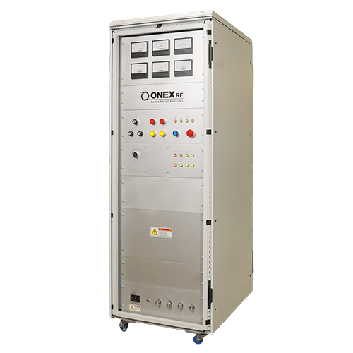
DC Volt Meter / 0-10vdc | Displays the set input voltage from the PLC or from the Generator control board in local mode. |
Forward Power Meter / 0-10KW | The forward Power meter displays the RF power sent to the RF welder. The meter receives the signal from the Solid State Amplifier.The Amplifier AGC converts the logarithmic signal from the RF Line Section Slugs (RF Sensors) to linear signal. |
Reflected Power Meter / 0-2.5KW | The reflected Power meter displays the reflected power from the load. The meter receives the signal from the Solid State Amplifier. The Amplifier AGC converts the logarithmic signal from the RF Line Section Slugs (RF Sensors) to linear signal. |
Grid Current Meter / 0-1A | Displays the Grid current during RF ON. The Grid Current limit is set at the factory based on the type of tube use. |
Plate Current Meter / 0-5A | Displays the Plate Current during RF stand by or operation. The Grid resting current may vary based on the tube time ranging from 150-300mA. The Plate Current limit is set at the factory based on the type of tube use. |
Plate Volt Meter / 0-10,000 VDC 4-10KW = 4500-6000 VDC) | Displays the Plate DC voltage before the High Voltage fuse. When the Fuse blows the system controller detects and disconnects AC voltage to the DC section. The DC voltage discharges through the discharge resistors. |
Local / Remote Mode SW | Selects the generator operation in Local Mode to control from the panel switches and in Remote Mode the generator is controlled from the PLC |
Knob-1 / RF ON Timer | RF-ON Timer functions in local mode and is activated when the RF output is set ON. The RF powers turns off after the timer times out. The timer is used for reference only. |
Knob-2 / RF-Power Control | The power control knob is used in Local Mode only, which sets the amplifier input voltage from 0-10vdc to increase the RF output power. The RF output is set 0 watt when the Knob-2 is adjusted all the way in CCW direction and Max Power when adjusted in CW direction. |
Hi-Voltage ON Red PB | The Hi-Voltage ON PB is active only in Local Mode. When pressed the Hi-voltage contactor turns ON the Plate Voltage in two steps (soft start). |
Hi-Voltage OFF Amber PB | The Hi-Voltage OFF PB is active only in Local Mode. When pressed the Hi-voltage contactor turns OFF the Plate Voltage. |
RF Power ON Red PB | The RF Power ON PB is active only in Local Mode and when the Plate voltage is ON. When pressed, the RF circuit will activate and RF power can be increased only by turning the RF Power control Knob-2 in CW direction (0-10vdc). |
RF Power OFF Amber PB | The RF Power OFF PB is active only in Local Mode. When pressed, the RF circuit will deactivate the RF power. |
Reset Blue PB | The reset button is active all the time and is for resetting the generator fault conditions or E-Stop condition. |
E-Stop Red Mushroom PB | E-stop PB is active in all conditions and intended for emergency shutdown, which is wired in series with the RF welder emergency circuit. When energized it interrupts the hi-voltage to the Plate and turns of the Solid State Amplifier Power. |
Ready-LED / Green or Red | Green - When all generator internal diagnostic circuit conditions are OK after pressing reset PB. Red - when any of the other LEDs are Red. When LED is red the generator will not turn HV on nor the RF PWR. |
VSWR LED / Green or Red | Green - When reflected power is low.. Red - when reflected power exceeds the factory set limit 10 or 20%. For some applications ONEX can set higher limits to overcome the Hi-REF spike condition errors due to some materials |
Overload-LED / Green or Red | Green - When all Plate current is below the factory set limit. Red - when Plate current exceeds 3.5 A, set at the factory, (for lower power generators the set point may be lower based on the Tube specs). |
Arc-LED / Green or Red | Green - When the generator power is ON and there is no Arc or short load to ground signal. Red - when arc detected during sealing cycle, The output power is immediately turned of to prevent any die damage. |
NO-RF Feedback -LED / Green or Red | Green - When Solid State Amplifier turns on and energizes the final stage amplifier it monitors the RF output signal feedback. If the feed back is normal the LED stays green. Red - when the RF final output feedback from the line section is not detect the the solid state driver stops the output. This feature is intended to prevent the RF output incremental rise due to lack of feedback signal, because the SS-Amp AGC role is to maintain the constant power output by increasing or decreasingthe first stage RF signal level. |
3 Phase - LED / Green or Red | Green - When all generator input power phases are OK and not swapped or interrupted individually. Red - when any of the 3-phase power lines does not detect voltage or the phases are swapped. |
Blower-LED / Green or Red | Green - When Blower is ON and the switch detects adequate air flow into the tube section. Red - when blower circuit is ON but the air flow switch is not energized by the blowing air flow or the blower is not working. |
Door Switch -LED / Green or Red | Green - When the generator back door is closed. Red - when generator back door is open or switch is loose when the door is closed. |
AMP-FAN -LED / Green or Red | Green - When Solid State amplifier is ON, the 3 Fans are blowing and the air flow switch (on the opposite side of the amplifier) detects . Red - when the RF amplifier is ON but Fans are Off or the Fans are ON but the switch is loose and does not detect adequate air flow. |
NO-RF FEEDBACK- LED / Green or Red | Green - When Solid State Amplifier turns on and energizes the final stage amplifier it monitors the RF output signal feedback. If the feed back is normal the LED stays green. Red - when the RF final output feedback from the line section is not detect the the solid state driver stops the output. This feature is intended to prevent the RF output incremental rise due to lack of feedback signal, because the SS-Amp AGC role is to maintain the constant power output by increasing or decreasingthe first stage RF signal level. |
Over-Temp - LED / Green or Red | Green - When SS Amplifier heat sink is at normal temperature. Red - when SS Amplifier heat sink is high, which is detected by a thermal switch internally mounted onto the heat sink |
AMP-SSR - LED / Green or Red | Green - When Solid State amplifier is turned ON, the Solid State Relay activates and supplies 40VDC to the SS-Amp. Red - when the SS RF Amplifier is OFF but SSR provides 40VDC to the SS-Amp that means the SSR could be shorted. The system will not function during this error condition |
Grid Current -LED / Green or Red | Green – When the Grid current is below the factory set limit during RF welding process. Red - When Grid current exceeds 500mA set at the factory (for low power generators the set point may lower based on the tube specifications) |
Hi-Voltage Fuse -LED / Green or Red | Green - When RF Hi-Voltage is turned ON and the Fuse is OK. Red - when the Hi-Voltage Fuse is blown. The fuse normally blows when the vacuum tube amplifier has internal arc or shorted. |
Tube Temp - LED / Green or Red | Green - When Generator is ON for long time and tube temperature is below of the externally mounted temperature probe set temperature. Red - When Generator is ON for long time and tube temperature exceeds externally mounted temperature probe set temperature. This is tested at ONEX RF and can be offered to customers as an option. |
Main Power Breaker | 3ph 100A Panel Breaker |
Power ON - LED / Green Indicator | Green LED ON - When the breaker is energized. The LED light stays ON for 2 minutes after turning the main power beaker to cool the tube. The timer is set internally on the bottom power section. |
Tube Blower / 6A Fuse White LED / OFF or ON | OFF– When the Fuse is OK. Generator is in normal working condition. ON– When the Fuse is Blown the Blower will not turn ON and the system will turn off the Hi-Voltage and RF Signal to the the tube. |
Filament Transformer / 10A Fuse White LED / OFF or ON | OFF– When the Fuse is OK. Generator is in normal working condition. ON– When the Fuse is Blown the Tube Filament will not function, NO RF Power out |
40VDC Power Supply / 10A Fuse White LED / OFF or ON | OFF– When the Fuse is OK. Generator is in normal working condition. ON– When the Fuse is Blown the Solid State Amplifier will not function |
24VDC Power Supply / 5A Fuse White LED / OFF or ON | OFF– When the Fuse is OK. Generator is in normal working condition. ON– When the Fuse is Blown the generator controls will not function |
For quick response, please provide details of your product, process needs, and full contact information.

For application related questions, you can always reach us by phone at +1(626)358-6639.
We offer excellent service:
We look forward to working with you soon.
EXPECT ONLY EXCELLENCE

ONEX RF Inc. is dedicated to giving you excellent service with quality results. Expect only excellence.
Copyright © 2020 ONEX RF . All rights reserved.Trademarks, including but not limited to ONEX RF Design are the trademarks or registered trademarks of ONEX RF and used under license by ONEX RF Based on mixed usage scenario.Terms of Use | Privacy Policy